
TL;DR you should build your own keyboard if you work with computers all day, every day…
look ma, no carpal tunnel
Table of Contents
The main problem is ergonomics, or rather, lack thereof, when typing at a computer for 8+ hours a day for years…
But there are also bad typing habits, and a split ortholinear ergonomic keyboard helps me replace them with good ones for the long term
Then there’s also a sense of pride of having built a tank keyboard yourself, fixing it if it ever breaks and customize it to your liking, as many times as you’d like, with perhaps different keycaps, different switches, different lights under each key, whatever tickles your fancy…
My solution(s) – ergonomic keyboards. More accurately – DIY split ergonomic mechanical keyboards.
And we’ll get into the why’s of each of these attributes in a minute.
Now, fair warning: the rabbit hole of custom mechanical keyboards goes very deep, and it may end up being a very expensive hobby.
Also, there are lots. of. split. diy. or. not. custom. and. customizable. mechanical. keyboards. out. there. And not having done anything like this before, my fancy settled on a couple of keyboards, primarily for the clever ideas in their design and function, as well as in their looks.
I mean who doesn’t want to feel like they command a starship when they’re coding silly things with cat videos in there…
WHY
- my subjective justification for doing any of this stuff is simply egotistical: curiosity and chasing those elusive happiness hormones that get released when doing something you’re proud of
- pros
- body posture and carpal tunnel avoidance
- repetitive stress injury avoidance
- improved typing speed (though marginal, if any at all)
- improved typing efficiency and less (if any) fatigue, especially during long typing sessions
- pleasure of typing on real-good-hardware™
- looks dope AF
- building something that you can always fix and customize is a priceless thing
- learning something new is (or at least should be) always great
bragging rights towards your grandchildren that you built something physical yourself…just kidding, nobody cares 🙂
- cons
- bit on the expensive side, all things considered, but an artisan uses the best tools, and doesn’t skimp on it, ever
- it’s actually far, far cheaper than buying pre-built with the same benefits, or customizability or features
- most people are off-put by having to solder stuff themselves, so they’d rather buy something pre-made, which then makes it prohibitive… so that’s the catch 22
- bit on the expensive side, all things considered, but an artisan uses the best tools, and doesn’t skimp on it, ever
As such, I’ve chosen to build the IRIS
In my humble opinion, it has everything going for it: split, custom, RGB, backlit, ergonomic, ortholinear with just-the-right-amount™ of thumb keyclusters (the keys are not staggered side to side like on a regular keyboard, but orthogonally, almost in a fairly square matrix, with the rows are offset to naturally match the shape of your stretched fingers), mechanical, open source everything, from the plates, to the pcb design to the wiring,
BUILD LOG
Parts needed and where to get them
Costs
- 2 PCB set: $17.99 (includes 2 Iris PCBs, 2 reset buttons, 2 TRRS jacks, 56 1N4148 diodes, 2 4.7kΩ resistors
- Arduino ProMicro set: $16 (2x $8)
- Kailh Copper Speed Switches (brown tactile): $16.80 (for 60 of them, need 56)
- Key Caps: $15-20 (for really cheap ABS plastic ones, up to you how much to spend)
- Iris Plates, aluminum: $27.99 (4 plates, 2 for each half, top and bottom, includes brass standoffs and screws for those)
- TRRS Cable: $2.49 (for halves to ‘talk’ to each other)
- MicroUSB cable: $2.99 (for the left half to connect to your computer)
- LED Support components: $2 (2 mosfets, and 2 4.7 kOhm resistors)
- (optional) 3mm LEDs: $6 ($CAD 7.50 for 60 of them)
- (optional) Under glow RGB strip: $6 (for 12 RGB LEDs)
Certain components like the Pro Micro controllers, the keycaps, switches, TRRS and microUSB cables, the LEDs (both RGB and mono color) can be had for cheaper on AliExpress, if you’re willing to wait up to 3 months for the packages to arrive.
The cost savings are not radically significant however. Maybe cheaper, but when you factor in everything else, like your time, not really.
Heck, you can pick any open source PCB design files and have them ‘printed’ on demand from various local electronics services. Same goes for the plates, you could have them milled or 3d printed locally, if you wanna go cheaper.
But counting shipping from many entities and the hassle of different timetables for each of them, the unprofessionalism of some of these suppliers, the time it takes to put all this together, I chose to do business with the folks that have designed the keyboard, and I am very happy about the choice.
Some useful resources, both written and video embedded
- the official build guide
- the troubleshooting guide
- Thomas Baart’s excellent writeup on the Iris and other keebs
- TaeKeyboards short video tutorial on building this, which I found to be excellent:
Things I’ve learnt during my build
(tips & tricks)
- bending led pins a bit before mounting to sit flush with the switches

- order of things
- source all the parts from the links above
- dust off the soldering iron and supplies
- put the diodes through the holes and bend their legs slighly so that they stay in place when soldering; careful to orient the diodes the right way, as they do have polarity, so the side with the black bar oriented to the bottom of the PCB in the case of the Iris, but it may differ in the case of other PCBs. It is usually marked clearly on the PCB what the orientation of the diodes should be
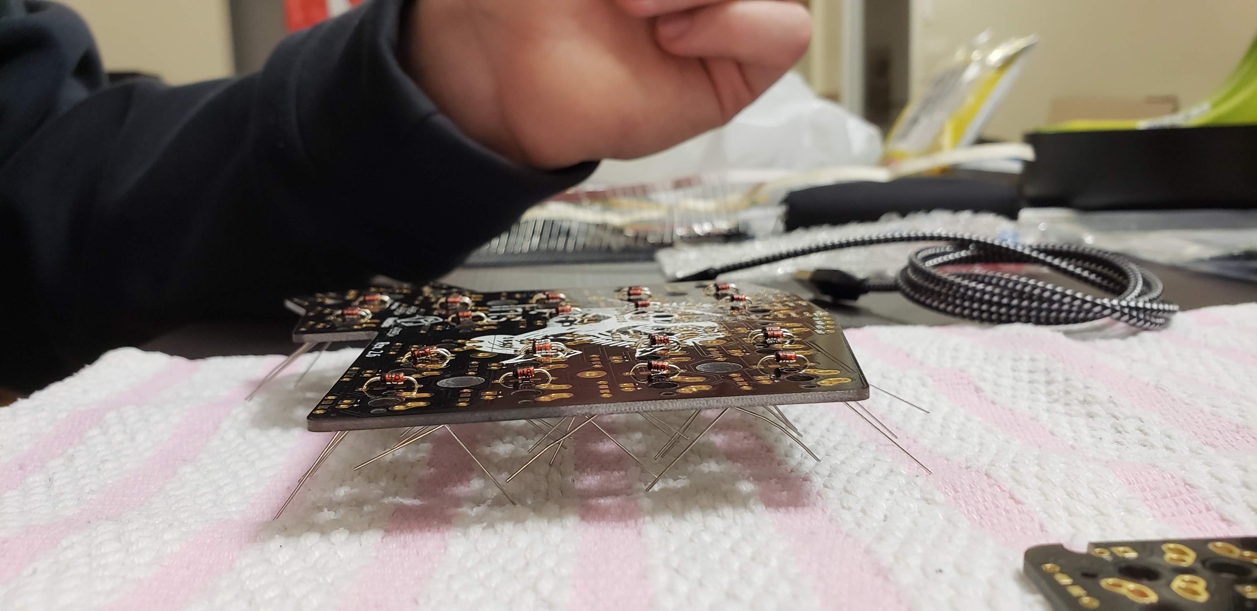

- solder the diodes, then cut the legs excess off with a pair of flush cutters, just above the solder joints on the back of the board; if you decide to make your controllers ‘hotswappable’ as well, then keep all the diode legs for later
- put the resistors for LEDs through the holes and bend their legs slightly, just like with the diodes at the steps above. Resistors don’t have polarity, and as such, their orientation doesn’t really matter, however, it looks nicer when they’re arranged symmetrically, in my humble opinion
- solder the resistors, then cut off the legs on the back of the board just like in the case of the diodes
- solder the MOSFETs and resistors for the underglow RGB lights; I found it easiest to apply flux and some solder tin on the PCB plate where the single leg side of the MOSFET would go, and solder that with a tiny amount of solder first, while holding it with a pair of tweezers in place in the correct position; then do the other two legs on the other side of the MOSFET
- solder the TRRS ports and the reset buttons onto the back of the PCB.
- flashing firmware onto the Arduino Pro Micros, both with the same firmare relevant for your keyboard, to make sure they are working before anything. See the flashing guide at https://docs.qmk.fm/#/newbs_flashing for how to build and flash your firmware. If you use ProMicros, and haven’t mucked about with replacing the standard bootloader, then it’s as easy as:
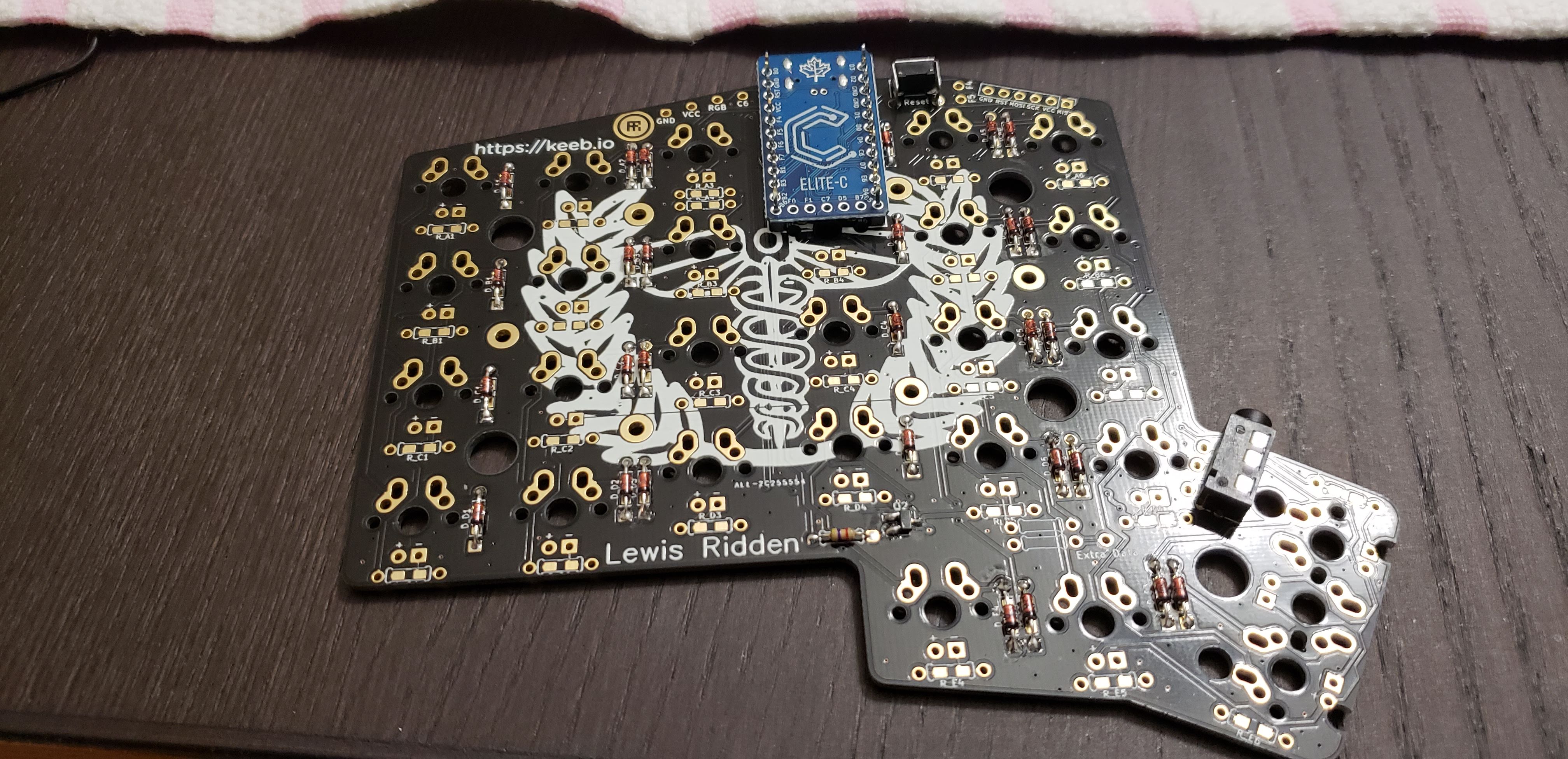
make iris/rev2:default:avrdude. If you have opted for the Elite-C microcontrollers, then it’smake iris/rev2:default:dfu - the ProMicro controllers usually come with a set of ‘legs’, with a hard plastic around them, so that it raises the controller from the actual PCB when mounted. Solder those legs onto the PCB first, and *don’t* solder the ProMicros yet. One trick is to solder those legs at a slight angle, so that the ProMicro can be press fitted against them, to make contact. Unless you actually solder the sockets instead of legs onto the PCB, there’s no reliable way to test if your controller and the traces on the PCB work as intended, before soldering the damn thing fixed in place. Notice in the pic that the set of pins on which the microcontroller is ‘resting’ (actually press fitted) is slightly bent in a very suble slope, like / \ . Just ever so slightly, so it makes contact with the controller board when press fitting that in, with a small amount of force. Keep in mind this is not a sure-fire way to get this done, and the most reliable way is to actually socket your microcontroller, and have sockets instead of those pins, but that’s for antoher time
- at this point solder the switches in, unless you have bought MillMax or Holtite sockets for your switches, in which case, come back later after I put together a how-to for those tiny bits, or find videos of how it’s done
- press fit the ProMicros onto your PCBs against the legs you’ve soldered on, and pray that they make full contact with the controller pads. Plug the cable into your computer, and press all the switches and see if they work correctly.
- if you went for backlighting, also insert the LEDs into their holes. The D in LED stands for diode, as such, mind the polarity. The longer leg of each LED should go in the whole marked with a ‘+’ sign on the PCB. Thus, the shorter leg in the hole marked with ‘-‘. Keep in mind that at this point, you still haven’t soldered in the microcontrollers, ProMicros or the Elite-C. You wanna press fit them one more time before soldering it in.
- If everything works, go ahead and permanently solder your ProMicros onto the PCB. Note that on the master half (the left one), the ProMicro’s chip and other components will have to be facing the PCB, so ‘smooth’ side toward you, since you’re working on the back side of the PCB. Also, keep in mind that some ProMicro clones come with some J1 jumper pads on their top left corner, near the usb port. Don’t short it, leave it open if it is. There has been some conjecture on soldering that jumper as connected/shorted. Because people think it made it run truly on 5 Volts. Since you’re feeding the keyboard from USB, you’ve only got 5 or less Volts, so leave it unsoldered/disconnected. Soldering simply lets the VCC pin bypass the built in voltage regulator, if you have a power source that is higher than what’s required. Again, leave it off. The other half (PCB) will have to have the Arduino Pro Micro or compatible clone flipped over, meaning, with it’s chips and electronic components facing you, and its ‘smooth’ side towards the PCB. Otherwise each individual half will work on it’s own, but not together, or if they happen to by some miracle, you’d have the left half working fine, and the right half weirdly mirrored. I found that out the hard way… /facepalm.
- socketing the Pro Micro using diode leg cutoffs and peel-away sockets, for some other time. After I get to do it again and take some valid pics of it.
RESULTS
- Pictures here: https://photos.app.goo.gl/DHKxFNfkBVPTuV9X7
- My keymap for this particular keyboard series is at: https://github.com/qmk/qmk_firmware/tree/master/keyboards/keebio/iris/keymaps/omgvee
- let me know in a comment if you want to hear a sound test. Or see me type on this thing…